

Next: Iodine absorption filter
Up: Receiver
Previous: Optics
Return to the Publications.
Return to the Index.
In order to increase the dynamical range of the HSRL, new photon
counting electronics were designed (Figure 8).
The photon counting data system has
three counters and each counter has 2 buffers,
one for each polarization.
Counting rates have been tested up to 350 MHz, but counters are designed to
operate up to  1 GHz. The 100 ns bin width enables a 15 m range resolution.
The 4 kHz laser repetition rate enables the use of 2333 range bins, which
can be used to probe the atmosphere up to 35 km.
The limiting factor of the data system is
the photomultipliers (EMI 9863B/100),
which allow counting only up to 15 MHz without significant
pile-up effects. The PMT's are pile-up and afterpulse tested and
both corrections are included to the data processing. The corrections
are discussed later in this chapter.
Computer control of the system is made by using Intel
80960CA embedded processor.
The user interface is realized by using a Sun Sparc Station II.
In addition to the data taking and the communication with
the Sun, the system processor is used to control
HSRL operation including pressure controlling of the etalons,
timing of the Pockels cell voltage, controlling of the seedlaser
temperature, controlling of the system shutters and relays, and
controlling of the WFOV aperture.
Most of the HSRL-operations are computer controllable from a
menu interface. System performance can be followed from real time
displays.
The real time Range Time Indicator (RTI) displays
for the raw and/or inverted data
are used to
display the incoming data so that altitude, variability, thickness
and depolarization of the cloud layer can be observed when
the clouds move over the lidar site. Similar displays for the
cloud optical properties (optical depth, aerosol backscatter cross section,
phase function) can be shown.

Figure 8: The HSRL data acquisition system.
The new counter design has improved the background light measurement
accuracy of the HSRL. Instead of interrupting the data taking every
3.5--7 min for
background and calibration checks
(as was made with the system described by Grund [10]),
the new HSRL is capable of measuring
the background light simultaneously with the data. The
maximum resolution of the data system is increased from 256
to 4096 range bins per channel. In the HSRL, the amount of background light
in the measurement is calculated from the measured profile by
using the upper altitudes of the lidar profile.
The signal together
with the background light is saved and therefore different
kind of background corrections can be studied. Currently, the measured
HSRL profiles are background corrected by assuming the
signal above
 33 km to be background. By averaging the upper range bins
together, the average amount of background in the measurement is calculated.
The disadvantage of the current background correction method is
that some of the signal can still be originated from Rayleigh scattering
leading into an overestimate of the amount of background light for
altitudes 33 km or higher. A development of a background correction
method that removes the Rayleigh scattering contribution from the
background is currently in progress.
Photomultiplier afterpulsing can be seen as multiple output counts
for a single input photon [30]. The afterpulsing could
be caused by positive electron production in the dynode chain.
The afterpulse pulses are
time delayed compared to the signal from incident photon and the
time delay is proportional to the path length for electron propagation.
The signal originated from
a short light pulse and
measured with
the HSRL can be presented in following form

where
 = signal measured with the HSRL
S(t') = signal incident on the receiver
 = signal responce function, that
contains
the laser pulse width,
datasystem bin width and
afterpulsing of the photomultiplier
The afterpulse probability distributions
were measured by illuminating the photomultiplier photocathode with a
short duration laser light pulse. Pulse counting rates less than one count
per 100 ns long data bin per pulse were used. A large number of laser
pulses were averaged ( 1 hour average). The probability distributions
were calculated from the background corrected data. The amount of
background light was calculated from the end of data record and
the average value was subtracted from data.
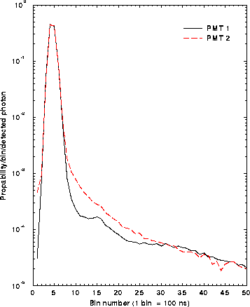
The measured
afterpulse probability distributions of two photomultiplier tubes
are presented in Figure 9.
The afterpulse
probability distribution was found to be different for each tube and
therefore a separate correction for each tube had to be implemented
to the signal analysis program. With a known afterpulse probability
distribution function, the afterpulse contribution can be removed from the
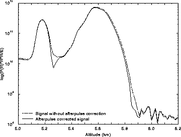
measured signal by using deconvolution. The effect of afterpulse correction to the
measured signal is presented in Figure 10.

Figure 9: The temporal distributions of two EMI 9863B/100 photomultiplier
tubes. The temporal distribution of the measured photons is
a convolution of the laser pulse width, bin width of the data system,
and the afterpulsing of the photomultiplier. The laser pulse is
located in the first bins and the afterpulse can be seen as a
decaying tail. The afterpulse distribution of the PMT1 shows
better afterpulse behavior than the PMT2.

Figure 10: The effect of afterpulse correction to the measured aerosol signal
in the case of thick water cloud (at 5.6 km) with an ice crystal precipitation at 5.1 km.
The afterpulsing increases the aerosol signal at the end of the cloud, and
therefore the geometrical thickness of the clouds is underestimated. The effect
of afterpulsing to the molecular signal is similar, and thus a slight overestimate
of the optical depth of the cloud is made, if the afterpulse correction is
not performed.
The pulse pile-up is seen when all time separated photons
are not distinguishable and they overlap.
This causes a nonlinear response.
In order to be able to separate between counts, a minimum
separation time between two pulses is required for them to
be distinguished. This time is called resolving time (or dead time).
Since the time
interval distribution of photons that reach the photomultiplier follow
a Poisson distribution, the probability  that a pulse
overlaps
with another pulse inside a certain time interval is given
by the following formula [31]

where
 = resolving time
R = average count rate
In order to obtain the resolving time (dead time) of the photomultipliers,
the photomultiplier responses to different count rates were tested.
First, light level is set to level which is high enough to generate a pile-up.
Then the photomultiplier response to different light levels is
measured by changing the light intensity with neutral density filters and
recording the signal change. In order to be able to define the resolving
time of the photomultiplier,
the photon counting was modeled.
The pulses coming from the photomultiplier were treated as Poisson
distributed signals.
The resolving time that produced
the best fit between simulated and measured results was used
for the pile-up correction. All photomultipliers were found to have
 13 ns resolving time. The pile-up correction has to be
performed before the afterpulse correction or any other corrections,
because the pile-up effect is nonlinear. The pile-up is affected by the
signal strength, signal background and afterpulsing and therefore,
data has to contain the information from all these factors
when the correction for pile-up
is performed.
In order to make the pile-up correction for
data, the following equation was used

where
N = measured counts
 = actual counts
 = resolving time
R = average count rate = 
This equation is solved iteratively for  , so that
1.  = N
= N
2. New  , where dt = bin length [s]
3. Step 2 is repeated until  converges
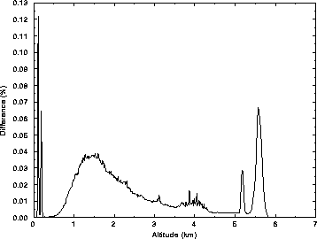
The effect of pile-up correction to the measured signal is presented in Figure 11.

Figure 11: The effect of pile-up correction to the measured aerosol signal
in the case of thick water cloud (at 5.6 km) with an ice crystal precipitation at 5.1 km.
The calibration fiber signals are shown as spikes at altitudes  0 km.
The maximum number of photons measured for the water cloud is 0.68 photons/100 ns bin
and after pile-up correction 0.75 photons/100ns bin are observed. Even with
this low count rates the effect of pile-up is
  10% and therefore,
the pile-up correction is very important when strong
returns from clouds are studied.


Next: Iodine absorption filter
Up: Receiver
Previous: Optics
Return to the Publications.
Return to the Index.
Paivi Piironen
Tue Mar 26 20:49:55 CST 1996
 1 GHz. The 100 ns bin width enables a 15 m range resolution.
The 4 kHz laser repetition rate enables the use of 2333 range bins, which
can be used to probe the atmosphere up to 35 km.
The limiting factor of the data system is
the photomultipliers (EMI 9863B/100),
which allow counting only up to 15 MHz without significant
pile-up effects. The PMT's are pile-up and afterpulse tested and
both corrections are included to the data processing. The corrections
are discussed later in this chapter.


 33 km to be background. By averaging the upper range bins
together, the average amount of background in the measurement is calculated.
The disadvantage of the current background correction method is
that some of the signal can still be originated from Rayleigh scattering
leading into an overestimate of the amount of background light for
altitudes 33 km or higher. A development of a background correction
method that removes the Rayleigh scattering contribution from the
background is currently in progress.

 = signal measured with the HSRL
S(t') = signal incident on the receiver
 = signal responce function, that
contains
the laser pulse width,
datasystem bin width and
afterpulsing of the photomultiplier
  1 hour average). The probability distributions
were calculated from the background corrected data. The amount of
background light was calculated from the end of data record and
the average value was subtracted from data.
The measured
afterpulse probability distributions of two photomultiplier tubes
are presented in Figure

 that a pulse
overlaps
with another pulse inside a certain time interval is given
by the following formula [
 = resolving time
  13 ns resolving time. The pile-up correction has to be
performed before the afterpulse correction or any other corrections,
because the pile-up effect is nonlinear. The pile-up is affected by the
signal strength, signal background and afterpulsing and therefore,
data has to contain the information from all these factors
when the correction for pile-up
is performed.

 = actual counts
  = resolving time
 , so that
 = N
= N
 , where dt = bin length [s]
 converges

 0 km.
The maximum number of photons measured for the water cloud is 0.68 photons/100 ns bin
and after pile-up correction 0.75 photons/100ns bin are observed. Even with
this low count rates the effect of pile-up is
  10% and therefore,
the pile-up correction is very important when strong
returns from clouds are studied.