 rad, which
further decreases the
background sky noise and
multiple scattering effects to the measured signal.


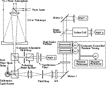
The backscattered light is collected using a 50 cm diameter telescope (see Figure 6). To avoid specular reflection from horizontally oriented ice crystals, the system pointing direction is tilted by 4 degrees from the zenith. The signal polarized parallel to the receiver polarization axis and the signal perpendicular to that are separated by using a polarization cube (see Figure 6). This cube separates the signal to the WFOV-channel (PMT 3) and to the spectrometer-channels (combined aerosol+molecular channel (PMT1) and molecular channel (PMT 2)). An extra polarization cube for both channels is used to clean up the cross polarization component of the received signal down to a level that makes accurate depolarization measurements possible.
The multiple
scattering
properties can be studied by using the WFOV-channel, while simultaneously
measuring the single scattering return with the
spectrometer channels.
A stepper motor driven aperture for the WFOV-channel enables field of
view variations between 0.224 and 4 mrad. An interference filter
with 1 nm bandpass
is used for the background filtering.
Because the field of view can be wide and the filter bandpass is broad,
the WFOV measurements are currently limited to night time.
The field of view of the spectrometer channels is 160  rad, which
further decreases the
background sky noise and
multiple scattering effects to the measured signal.
In order to achieve daytime measurements with the spectrometer channels,
a low resolution etalon pair and
an 1 nm interference filter
are used to suppress the background solar
radiance.
The bandpass of the etalon pair is  9 pm, which is about 3 times
the width of
the expected Doppler broadened molecular spectrum.
The length of the
spacers is chosen so that only one common transmission order for
the etalon pair occurs inside the interference filter bandpass.
The bandpass of the low resolution etalon pair is wider than
in earlier systems [8,12]
in order to decrease the system sensitivity
for the drift between transmitter wavelength and the etalon
transmission maximum.
The effects of environmental changes to the etalon performance
are eliminated by mounting each etalon into a separate pressure
and temperature controlled chamber.
A third etalon chamber is used
as a pressure reference. The absolute pressure in reference
chamber and the differential pressures in each etalon chamber are
maintained by a computer controlled servo loop.
The etalons are operated near the pressure where the changes in tuning gas
density with temperature are cancelled by the thermal expansion of the
etalon spacers [29]. Nitrogen is used as a tuning gas.

Figure 6:
A polarizing prism at the output of the telescope separates the
orthogonally polarized signals between wide field of view channel (PMT3)
and the spectrometer channels (PMT1 and PMT2). Since the polarization
of the transmitted laser pulse is rotated by 90 between laser
pulses, each channel alternatively receives perpendicular and parallel
components.
The received backscatter
signal is prefiltered with an interference filter and a low resolution
etalon pair before being directed into a beam splitter.
The signal
detected with PMT1 contains the information about the total
aerosol and molecular backscatter signal. The signal directed through
the iodine cell and detected
by PMT2 is a combination of a amount of aerosol backscatter
signal which passes through the absorption cell and the wings
of the molecular backscatter signal.
After background filtering, the signal is divided into two channels by a beam splitter. The signal detected with the PMT1 (combined aerosol+molecular channel) contains the information about the total aerosol and molecular backscatter signal. The signal directed through the 43 cm long iodine cell and detected by the PMT2 (molecular channel) is a combination of the small amount of aerosol backscatter signal, which passes through the absorption cell, and the wings of the molecular backscatter signal (see Figure 7). The iodine absorption cell is described in more detail in Chapter 4.
A beamsplitter with a 30/70 (trans./refl.) splitting ratio is used to divide the signal between PMT1 and PMT2. The beam splitting ratio is chosen from the commercially available beamsplitters so that a good photon counting statistics with both channels is achieved when the system is tuned to the iodine absorption peak. Some beamsplitter types have poor transmission and reflection efficiencies and therefore part of the signal is lost in the beamsplitting process. Because good system transmission is important, a beam splitter with a high transmission and reflection efficiencies was chosen.
The beam splitters are highly polarization sensitive elements.
When linearly polarized laser beam interacts with atmospheric
aerosols and molecules, the backscatter signal consist
of two perpendicularly polarized components. Therefore,
the polarization sensitivity of the beamsplitter transmission
and reflection has to be taken into account. The polarization
sensitivity of the beamsplitter performance is noted as
a problem in a system described by Krueger et al. [17].
The advantage of the HSRL is that the received signal
is polarization filtered and therefore the light coming from the atmosphere
to the beam splitter is always incident with the same polarization.
On the contrary, the light from the current calibration light
source is polarized orthogonally to the lidar signal and therefore the
polarization sensitivity of the beam splitter creates a
problem. This problem is solved by generating a circularly polarized
light for the beamsplitter with a  -waveplate.

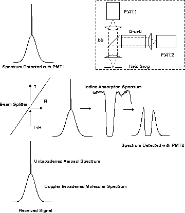
Figure 7: The spectral response of the HSRL receiver. The
insert figure at the upper right corner shows a simplified setup of the
spectrometer channels. The light that passes the field stop
contains information about the Doppler-broadened molecular
spectrum and the aerosol backscatter spectrum.
The signal is divided into two parts with the beam splitter.
The signal, which is transmitted
through the beam splitter is detected with PMT1 and it contains
information from the total backscatter signal. The signal, that
reflects from the beam splitter is directed through an iodine absorption
cell. In this process, the aerosol backscatter signal is attenuated
in the iodine absorption line.
Also the central parts of the molecular spectrum
are filtered out and therefore the signal detected with PMT2 is
a combination of the wings of the molecular spectrum and that
part of the aerosol backscatter signal that passes through the cell.


