Return to the Publications.
Return to the Index.
Data given in Figure 22 showed that the least particle
size dependent microwindow, for ice spheres, is near 920
cm![]() . Therefore, one would expect HSRL derived
brightness temperatures to agree with AERI measured values near this
region, and exhibit a decrease in correlation away from this region.
This should be more apparent within the microwindows located above
1000 cm
. Therefore, one would expect HSRL derived
brightness temperatures to agree with AERI measured values near this
region, and exhibit a decrease in correlation away from this region.
This should be more apparent within the microwindows located above
1000 cm![]() , where the
absorption is weak and more sensitive to particle size.
Four microwindows have been chosen for this comparison: a pair of strong
absorption regions at 811 and 820 cm
, where the
absorption is weak and more sensitive to particle size.
Four microwindows have been chosen for this comparison: a pair of strong
absorption regions at 811 and 820 cm![]() ; the cross-over
point at 934 cm
; the cross-over
point at 934 cm![]() ; and
a weak absorption region at 1096 cm
; and
a weak absorption region at 1096 cm![]() .
.
Figure 23 illustrates the HSRL derived brightness
temperature (dashed lines) relative to AERI data (solid lines) for the
strong absorption regions located at 811 cm![]() (upper)
and 820 (lower) cm
(upper)
and 820 (lower) cm![]() on 17 November 1994. The results are based on the Mie
calculated optical depth ratios in Figure 22. The
shaded region within the dashed lines accounts for the difference
between 25 and 100
on 17 November 1994. The results are based on the Mie
calculated optical depth ratios in Figure 22. The
shaded region within the dashed lines accounts for the difference
between 25 and 100 ![]() m particles. The HSRL derived 820 cm
m particles. The HSRL derived 820 cm![]() microwindow
shows similar agreement with AERI measurements as the 811 cm
microwindow
shows similar agreement with AERI measurements as the 811 cm![]() microwindow, while demonstrating an opposite bias from the baseline
temperature.
Figure 22 shows similar disagreement between the 811 and 820
cm
microwindow, while demonstrating an opposite bias from the baseline
temperature.
Figure 22 shows similar disagreement between the 811 and 820
cm![]() visible to infrared OD ratios,
where the 811 cm
visible to infrared OD ratios,
where the 811 cm![]() experimental results appear to disagree with the trend
demonstrated by the other data.
experimental results appear to disagree with the trend
demonstrated by the other data.
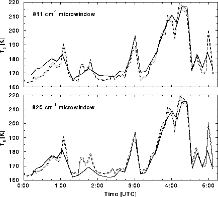
Figure 23: HSRL derived brightness temperature (dashed lines) relative to
AERI measured values (solid lines) for 811 cm![]() (upper) and 820 cm
(upper) and 820 cm![]() (lower) microwindows on 17 November 1994,
Madison. The shaded regions between the dashed lines represents the
shift in derived brightness temperature due to a change from 25 to 100
(lower) microwindows on 17 November 1994,
Madison. The shaded regions between the dashed lines represents the
shift in derived brightness temperature due to a change from 25 to 100
![]() m particle sizes.
m particle sizes.
Figure 24 is similar to
Figure 23 but illustrates results for the 934 cm![]() (upper) and 1096 cm
(upper) and 1096 cm![]() (lower) microwindows on 17 November 1994.
The deviation in expected brightness temperature is minimal at 934
cm
(lower) microwindows on 17 November 1994.
The deviation in expected brightness temperature is minimal at 934
cm![]() , whereas the 1096 cm
, whereas the 1096 cm![]() microwindow exhibits a large dependence on
particle size. This is consistent with the Mie calculations shown in
Figure 22. HSRL derived
brightness temperatures are also in close agreement within these
microwindows. The largest discrepancies in the data (near 01:45, 03:00 and
05:00 UTC) are due to the instrumental characteristics discussed in
Section 4.1. This particular case was favorable because
the clouds never become opaque.
microwindow exhibits a large dependence on
particle size. This is consistent with the Mie calculations shown in
Figure 22. HSRL derived
brightness temperatures are also in close agreement within these
microwindows. The largest discrepancies in the data (near 01:45, 03:00 and
05:00 UTC) are due to the instrumental characteristics discussed in
Section 4.1. This particular case was favorable because
the clouds never become opaque.
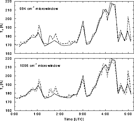
Figure 24: HSRL derived brightness temperature (dashed lines) relative to
AERI measured values (solid lines) for 934 cm![]() (upper) and 1096 (lower) microwindows on 17 November 1994,
Madison. The shaded regions between the dashed lines represents the
shift in derived brightness temperature due to a change from 25 to 100
(upper) and 1096 (lower) microwindows on 17 November 1994,
Madison. The shaded regions between the dashed lines represents the
shift in derived brightness temperature due to a change from 25 to 100
![]() m particle sizes. Both regions compare well with AERI measured
results. Note the reduced uncertainty in the 934 cm
m particle sizes. Both regions compare well with AERI measured
results. Note the reduced uncertainty in the 934 cm![]() microwindow as
a function of particle size. This is consistent with the analysis of
Figure 22.
microwindow as
a function of particle size. This is consistent with the analysis of
Figure 22.
The case of 9-10 November 1995 did become opaque, between 2:30 and
3:30 UTC. This is apparent in Figures 12 and
15. Brightness temperature data for the 934 cm![]() microwindow is given in Figure 25, shown relative to the
HSRL measured optical depth (bottom). The two instruments
exhibit good correlation until 2:30 UTC, where the cirrus becomes
opaque (shaded region).
microwindow is given in Figure 25, shown relative to the
HSRL measured optical depth (bottom). The two instruments
exhibit good correlation until 2:30 UTC, where the cirrus becomes
opaque (shaded region).
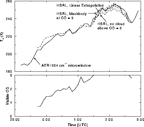
Figure 25: Upper figure shows HSRL derived brightness temperature as a
function of time at 934
cm![]() (dashed line) relative to AERI measured values (solid) on 9-10
November 1995 at Madison. Shaded portion of figure represents an HSRL
observed opaque cloud. Lower figure illustrates HSRL measured visible
column optical depth.
(dashed line) relative to AERI measured values (solid) on 9-10
November 1995 at Madison. Shaded portion of figure represents an HSRL
observed opaque cloud. Lower figure illustrates HSRL measured visible
column optical depth.
Calculation of vertically integrated radiance is performed until the cloud becomes opaque. The visible optical depth above this altitude must be approximated to continue calculation of the column integrated radiance. Three values are determined for this region: a minimum radiance, assuming the cloud terminates where it becomes opaque; a linearly extrapolated value, continuing the calculation based on the change in optical depth over the last 1 km; and a maximum radiance, assuming a blackbody emitter above the opaque point. The AERI measured data shows better agreement when the data is extrapolated, Figure 25.
HSRL and AERI brightness temperature calculations show good correlation
over a 100 K temperature range. Figure 26 illustrates data from
all cirrus cases for the 934 cm![]() microwindow, where HSRL data was
interpolated to coincide with
AERI times. The dashed lines represent a 5 K deviation from perfect
correlation between the instruments. All data points are shown,
including those that required extrapolation due to opaque cloud
cover. The upward trend in the data is a result of the linear
extrapolation of HSRL optical depth when the cloud becomes opaque,
which tends to underestimate the optical depth and, therefore, the
derived brightness temperature relative to the AERI measured values.
microwindow, where HSRL data was
interpolated to coincide with
AERI times. The dashed lines represent a 5 K deviation from perfect
correlation between the instruments. All data points are shown,
including those that required extrapolation due to opaque cloud
cover. The upward trend in the data is a result of the linear
extrapolation of HSRL optical depth when the cloud becomes opaque,
which tends to underestimate the optical depth and, therefore, the
derived brightness temperature relative to the AERI measured values.

Figure 26: AERI and HSRL derived brightness temperature data for the cirrus cases
given in Table 3 for the 934 cm![]() microwindow. Dashed lines
represent 5 K deviation from perfectly correlated instrument data.
microwindow. Dashed lines
represent 5 K deviation from perfectly correlated instrument data.
HSRL derived radiance can be utilized to determine a weighted visible to
infrared optical depth ratio, ![]() . This is accomplished by
iterating
. This is accomplished by
iterating ![]() , Section 2.2.4, until the HSRL
derived radiance agrees with AERI measured values to within 0.001
mW (m
, Section 2.2.4, until the HSRL
derived radiance agrees with AERI measured values to within 0.001
mW (m ![]() sr cm
sr cm![]() )
)![]() , rather than using
, rather than using ![]() derived in Section 4.1. This should yield an improvement
relative to the results determined in Section 4.1, which were
based on a direct ratio of HSRL measured visible
to AERI derived infrared optical depth. The previous approach assumes
a uniform cloud extinction cross-section to determine the IR optical
depth. This method inherently weights the cloud extinction
cross-section, given the HSRL vertical
resolution. Figure 27 illustrates the values of
derived in Section 4.1. This should yield an improvement
relative to the results determined in Section 4.1, which were
based on a direct ratio of HSRL measured visible
to AERI derived infrared optical depth. The previous approach assumes
a uniform cloud extinction cross-section to determine the IR optical
depth. This method inherently weights the cloud extinction
cross-section, given the HSRL vertical
resolution. Figure 27 illustrates the values of
![]() derived for all spectral microwindow regions for the
data cases given in Table 3.
derived for all spectral microwindow regions for the
data cases given in Table 3.
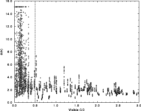
Figure 27: Visible to infrared optical depth ratio, ![]() , comprising all
spectral microwindows for the data cases listed in
Table 3. Regions of small optical depth (visible OD <
0.5) yield large uncertainties in
, comprising all
spectral microwindows for the data cases listed in
Table 3. Regions of small optical depth (visible OD <
0.5) yield large uncertainties in ![]() due to ill conditioned
solutions. Additional errors result from instrument field of view
differences. The dashed line represents a constraint on the data which
was used to derive the final value of
due to ill conditioned
solutions. Additional errors result from instrument field of view
differences. The dashed line represents a constraint on the data which
was used to derive the final value of ![]() .
.
Errors in determining ![]() are reduced by constraining the
data. An upper limit of 15.0 is placed on the
are reduced by constraining the
data. An upper limit of 15.0 is placed on the ![]() iteration, due to
inconsistencies between the instruments for small optical depths. Data with a
visible optical depth less than 0.5 are removed from the analysis,
shown by the dashed line in Figure 27. Instrument
field of view differences also yield discrepancies in some of the
data. This is apparent when the cloud cover within the field of view
is not uniform, Figure 28, resulting in the spatial
averaging problems discussed in
Section 4.1. When this occurs the HSRL derived column radiance
does not correlate with AERI data, resulting in a non-physical visible
to infrared optical depth ratio. Small breaks in near-uniform cloud
cover often underestimate
iteration, due to
inconsistencies between the instruments for small optical depths. Data with a
visible optical depth less than 0.5 are removed from the analysis,
shown by the dashed line in Figure 27. Instrument
field of view differences also yield discrepancies in some of the
data. This is apparent when the cloud cover within the field of view
is not uniform, Figure 28, resulting in the spatial
averaging problems discussed in
Section 4.1. When this occurs the HSRL derived column radiance
does not correlate with AERI data, resulting in a non-physical visible
to infrared optical depth ratio. Small breaks in near-uniform cloud
cover often underestimate ![]() ; whereas spatially-small,
optically-thick clouds in an otherwise clear sky
overestimate
; whereas spatially-small,
optically-thick clouds in an otherwise clear sky
overestimate ![]() . This is a result of the large AERI field
of view relative to the HSRL.
. This is a result of the large AERI field
of view relative to the HSRL.

Figure 28: Visible to infrared optical depth ratio, ![]() , (upper
curve) as a function of time, relative to the visible optical depth
(lower curve), at 934 cm
, (upper
curve) as a function of time, relative to the visible optical depth
(lower curve), at 934 cm![]() for 17 November 1994 data.
for 17 November 1994 data.
Figure 28 shows the variation in ![]() (934 cm
(934 cm![]() )
as a function of time for data acquired on 17 November 1994. The lower
figure illustrates the HSRL measured visible optical depth which was
used to derive the values in the upper figure. The regions of increased
slope in the lower figure represent temporal changes within the HSRL field of
view. The larger AERI field of view and increased dwell time yield
radiance measurements that will differ from HSRL derived values.
Cases with increased spatial uniformity (e.g., 10 November 1995) will
produce reduced scatter in the data, increasing the number of
available data points for an improvement in the final statistical
analysis. This is evident in Figure 29, which
contrasts the results of 17 November 1994 against the other cases.
)
as a function of time for data acquired on 17 November 1994. The lower
figure illustrates the HSRL measured visible optical depth which was
used to derive the values in the upper figure. The regions of increased
slope in the lower figure represent temporal changes within the HSRL field of
view. The larger AERI field of view and increased dwell time yield
radiance measurements that will differ from HSRL derived values.
Cases with increased spatial uniformity (e.g., 10 November 1995) will
produce reduced scatter in the data, increasing the number of
available data points for an improvement in the final statistical
analysis. This is evident in Figure 29, which
contrasts the results of 17 November 1994 against the other cases.
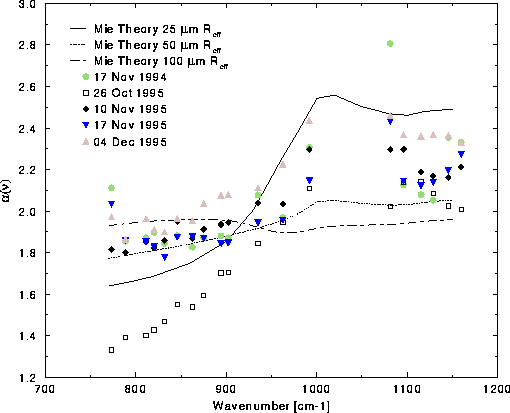
Figure 29: Spectral visible to infrared optical depth data for individual
data cases listed in Table 3. The cases that are not
shown did not have data within the constraints given in
Figure 27. Data from 26 October 1995 appears to be
underestimated due to the presence of opaque, low-altitude mixed phase
clouds.
A spectral comparison of ![]() data for individual cases is
given in Figure 29 relative to Mie theory. Three of
the eight cases listed in
Table 3 are not shown because data did not include
visible optical depths greater than 0.5 during the data acquisition period.
The results from 17 November 1994 (green circles) in
Figure 29, exhibited the largest scatter of the cases
shown. This was expected given the non-uniformity in cloud cover, and
optical depth, indicated in Figure 28. The anomalous
26 October 1995 data (open squares), where
data for individual cases is
given in Figure 29 relative to Mie theory. Three of
the eight cases listed in
Table 3 are not shown because data did not include
visible optical depths greater than 0.5 during the data acquisition period.
The results from 17 November 1994 (green circles) in
Figure 29, exhibited the largest scatter of the cases
shown. This was expected given the non-uniformity in cloud cover, and
optical depth, indicated in Figure 28. The anomalous
26 October 1995 data (open squares), where ![]() appears to be
underestimated between 750 and 900 cm
appears to be
underestimated between 750 and 900 cm![]() , is likely due to the HSRL
telescope configuration which has its focus at infinity. This yields
an overlap region between the transmitter and receiver for the first
2.5 km from the surface. The 26 October 1995 case consisted of optically
thick ice and mixed phase clouds (shown by HSRL), with a cloud base
altitude that varied between 2
and 4 km, which became opaque to the HSRL. This resulted in a visible
optical depth measurement that was less than expected, which
underestimated the visible to optical depth ratio. The HSRL is capable
of such measurements if a refocusing lens is placed in the telescope.
This will effectively reduce the receiver and transmitter
overlap region. The remaining cases
show good agreement relative to one another. Note that the least scatter in
the data among all spectral regions occurs at 934 cm
, is likely due to the HSRL
telescope configuration which has its focus at infinity. This yields
an overlap region between the transmitter and receiver for the first
2.5 km from the surface. The 26 October 1995 case consisted of optically
thick ice and mixed phase clouds (shown by HSRL), with a cloud base
altitude that varied between 2
and 4 km, which became opaque to the HSRL. This resulted in a visible
optical depth measurement that was less than expected, which
underestimated the visible to optical depth ratio. The HSRL is capable
of such measurements if a refocusing lens is placed in the telescope.
This will effectively reduce the receiver and transmitter
overlap region. The remaining cases
show good agreement relative to one another. Note that the least scatter in
the data among all spectral regions occurs at 934 cm![]() . However, all
spectral regions exhibiting strong absorption (below 1000 cm
. However, all
spectral regions exhibiting strong absorption (below 1000 cm![]() ) show
minimal scatter, aside from the anomalous 04 December 1995 case.
) show
minimal scatter, aside from the anomalous 04 December 1995 case.
Figure 29 illustrates that experimental values of
![]() for the individual data cases are consistent with Mie
theory for 50 to 100
for the individual data cases are consistent with Mie
theory for 50 to 100 ![]() m radius particles for wavenumbers smaller
than 900 cm
m radius particles for wavenumbers smaller
than 900 cm![]() , but consistent with 25 to 50
, but consistent with 25 to 50 ![]() m radius particles
for wavenumbers larger than 900 cm
m radius particles
for wavenumbers larger than 900 cm![]() . This suggests that the entire
experimental curve is biased toward larger values of
. This suggests that the entire
experimental curve is biased toward larger values of
![]() . Analysis of Equation 31 indicates that there
are five possible explanations for the apparent bias: HSRL measured
cloud visible optical depth was overestimated; FASCOD3P calculated
clear sky radiance was overestimated; AERI measured downwelling column
radiance was overestimated; field of view differences between the
instruments yield uncorrelated observations; or limitations of Mie
assumptions. The last factor is expected to be negligible in all but
specific cases (e.g., a given orientation of ice crystals).
. Analysis of Equation 31 indicates that there
are five possible explanations for the apparent bias: HSRL measured
cloud visible optical depth was overestimated; FASCOD3P calculated
clear sky radiance was overestimated; AERI measured downwelling column
radiance was overestimated; field of view differences between the
instruments yield uncorrelated observations; or limitations of Mie
assumptions. The last factor is expected to be negligible in all but
specific cases (e.g., a given orientation of ice crystals).
The first three possibilities are inconsistent with instrumental characteristics and measured results. Figure 18 demonstrated HSRL measurement errors due to multiply-scattered return within the HSRL field of view. However, this effect would yield a larger than expected return signal, which corresponds to an underestimate in the measured visible optical depth. FASCOD3P calculations within the microwindow regions also underestimate the radiance relative to AERI measured values, and the Gamma correction minimizes the model errors. The small uncertainty in the AERI measurements eliminates the third possibility.
The bias in the ![]() results was likely due to AERI and HSRL
instrumental differences. Field of view differences between the
instruments were shown to account for large errors during non-uniform
cloud cover cases. One would expect the field of view differences to
average over a large data set. However, this is not possible given the
data analysis constraint imposed on data with a visible optical depth
less than 0.5. For cases where the HSRL field of view is full and the
AERI FOV is partially clear,
results was likely due to AERI and HSRL
instrumental differences. Field of view differences between the
instruments were shown to account for large errors during non-uniform
cloud cover cases. One would expect the field of view differences to
average over a large data set. However, this is not possible given the
data analysis constraint imposed on data with a visible optical depth
less than 0.5. For cases where the HSRL field of view is full and the
AERI FOV is partially clear, ![]() is overestimated because
the AERI measured radiance is less than the HSRL derived
radiance. Cases where the HSRL FOV observes a clear data point while
the AERI FOV is partially clear would be ignored because the visible
optical depth value is less than 0.5. The spectral bias in
is overestimated because
the AERI measured radiance is less than the HSRL derived
radiance. Cases where the HSRL FOV observes a clear data point while
the AERI FOV is partially clear would be ignored because the visible
optical depth value is less than 0.5. The spectral bias in
![]() is quite apparent when combining all data points,
Figure 30.
is quite apparent when combining all data points,
Figure 30.
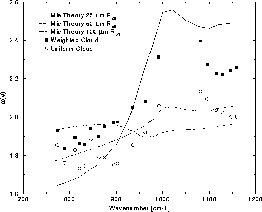
Figure 30: Similar to Figure 22, but updated with
![]() using weighted data from all cases. The weighted data
(solid squares) produces values that are more consistent with the Mie
theory results. The data implies an average radius of about 35
using weighted data from all cases. The weighted data
(solid squares) produces values that are more consistent with the Mie
theory results. The data implies an average radius of about 35
![]() m, assuming spherical particles. Individual spectral results for the
experimental data are given in Tables 4 and 5.
m, assuming spherical particles. Individual spectral results for the
experimental data are given in Tables 4 and 5.
The data from all cases, except 26 October 1995, were combined to
determine the effectiveness
of iterating ![]() from a weighted cloud distribution,
relative to the uniform cloud solution, and compared to Mie
theory. The weighted results are shown in Figure 30
(solid squares) and demonstrate less scatter than the unweighted
results (open circles). The weighted results are also more
consistent with the Mie theory calculations, indicating a mean
particle effective radius of roughly 35 to 40
from a weighted cloud distribution,
relative to the uniform cloud solution, and compared to Mie
theory. The weighted results are shown in Figure 30
(solid squares) and demonstrate less scatter than the unweighted
results (open circles). The weighted results are also more
consistent with the Mie theory calculations, indicating a mean
particle effective radius of roughly 35 to 40 ![]() m, assuming
spherical particles. Table 5 lists
m, assuming
spherical particles. Table 5 lists ![]() for
the weighted cloud experimental solutions for each of the microwindow
regions.
for
the weighted cloud experimental solutions for each of the microwindow
regions.
|
Microwindow | |
Microwindow | |
| 773.12 788.55 811.21 820.13 831.70 845.69 862.32 875.10 894.14 902.10 |
1.7396 1.6888 1.7337 1.7189 1.7263 1.8035 1.7759 1.8292 1.8774 1.8805 | 934.88 962.37 991.78 1080.97 1095.68 1115.21 1128.71 1145.34 1159.56 | 1.9731 2.0332 2.2421 2.2804 2.2210 2.1915 2.1730 2.1738 2.1762 |
It is necessary to stress the importance of the Gamma correction on the data in the previous figures. The downwelling atmospheric column radiance within a microwindow, given optically thin cirrus or clear conditions, is small relative to optically thick cirrus. As a result, the FASCOD3P calculated radiance from below the cloud dominates the HSRL derived radiance from within the cloud for optically thin or clear conditions. The disagreement between AERI measured radiance and FASCOD3P calculated radiance is significant for these cases. The Gamma technique, detailed in Section 2.1.2, accounts for the difference between AERI and FASCOD3P radiances under clear conditions to correct this problem for all conditions. Figure 31 illustrates the relative radiance difference and absolute brightness temperature difference due to the Gamma correction for 17 November 1994 data This is shown as a function of time given a variable, HSRL measured, visible optical depth.
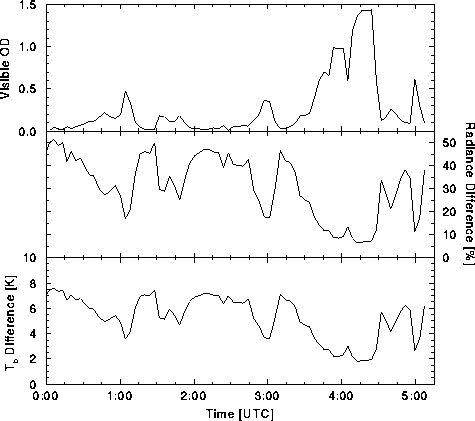
Figure 31: Effects of Gamma correction on HSRL derived brightness
temperature for 17 November 1994 data. The upper curve illustrates the
HSRL measured visible optical depth. The middle
curve shows the contribution of FASCOD3P calculated clear sky radiance
relative to the total column. The lower curve gives the absolute
difference in brightness temperature that would result without without
the use of the Gamma correction. The radiance and brightness
temperature curves are for the 1096 cm![]() microwindow.
microwindow.
The upper curve in Figure 31
indicates the HSRL measured visible optical depth as a function of
time. This demonstrates the magnitude of error for optically thin
relative to optically thick cirrus. Note that the Gamma corrected
radiance, middle curve, can contribute as much as 50 percent of
the total column
radiance. That implies that the AERI measured clear sky radiance and
FASCOD3P calculated clear sky radiance differ by two fold. Although
the absolute radiance difference is small, the effect is large for
optically thin cirrus or clear conditions. The total difference in
HSRL derived brightness temperature is given in the lower curve of
Figure 31, resulting in over 7 K difference for clear sky
conditions. The radiance and brightness temperature differences are
given for the 1096 cm![]() microwindow region.
microwindow region.
The errors associated with the brightness temperature calculations are
similar to those for the optical depth inversions given in
Section 4.1. The remainder of this section will detail the
magnitude of expected error given the FASCOD3P uncertainties shown in
Figure 20. Figure 32 illustrates the
FASCOD3P derived clear sky radiance relative to HSRL derived column radiance
within the 934 cm![]() microwindow for data acquired on 9-10 November 1995.
The model clear sky radiance contributes up to 50 percent of the total
derived radiance for optically thin cirrus conditions prior to 00:00
UTC. Note that the AERI measured clear sky column radiance near 23:30
UTC is similar to the FASCOD3P calculated values, as expected.
microwindow for data acquired on 9-10 November 1995.
The model clear sky radiance contributes up to 50 percent of the total
derived radiance for optically thin cirrus conditions prior to 00:00
UTC. Note that the AERI measured clear sky column radiance near 23:30
UTC is similar to the FASCOD3P calculated values, as expected.
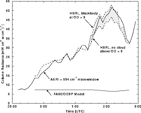
Figure 32: Comparison of measured and derived radiances for 9-10 November
1995. FASCOD3P contribution is shown to gauge the magnitude of clear sky
radiance relative to cloud values. The decrease in FASCOD3P calculated
radiance occurs with the decrease in cloud base altitude. HSRL derived values
are indicated by the dashed lines, where the shading depicts opaque
cloud cover.
Figure 33 shows the HSRL derived brightness temperature and expected error corresponding to the measured radiance and expected error given in Figure 20. The data corresponds to an HSRL measured visible optical depth of 0.5 for data acquired on 17 November 1994. The upper figure gives the HSRL measured brightness temperature (lower curve) and maximum expected brightness temperature (upper curve) based on FASCOD3P calculations derived from radiosonde uncertainties. The lower figure illustrates the absolute brightness temperature difference of the upper figure. This further suggests the importance of FASCOD3P calculations and radiosonde uncertainties to the final data products.
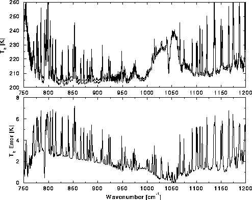
Figure 33: Upper figure shows HSRL derived brightness temperature (lower
line) and maximum expected brightness temperature (upper line),
given the radiance errors illustrated in
Figure 20, for data acquired on 17 November 1994.
The lower figure gives the absolute brightness temperature difference
for the values shown in the upper figure. The
resultant error is calculated for an AERI measured IR optical depth of 0.5